A dust collection system should be sized from the emission source outward. First determine the airflow needed at each hood, then verify duct transport velocity, calculate the incoming dust mass, and select enough filter area for stable operation.
The fan must deliver the required airflow at the total system pressure loss under normal loaded-filter conditions. Choosing equipment only by rated airflow can lead to weak capture, blocked ducts or excessive filter resistance.
How Much Airflow Is Required?
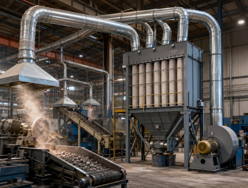
The airflow of an industrial dust collector system depends on the hood opening, enclosure design, distance from the source and the way dust is released.
For enclosed equipment, airflow can be estimated using:
Airflow = hood opening area × required inward velocity
A hood installed close to the source usually needs less airflow than an open canopy hood. Improving enclosure design is often more effective than simply installing a larger fan.
When several pickup points are connected, add only the airflow of sources that operate at the same time. Excessive safety margins can increase energy consumption and filter loading.
What Duct Velocity Keeps Dust from Settling?
The duct must maintain enough velocity to carry particles to the collector.
Fine dust generally requires less conveying velocity than coarse, dense or abrasive particles. If the velocity is too low, dust can accumulate in horizontal ducts and elbows. If it is too high, duct wear, noise and fan power increase.
Duct diameter should therefore be selected according to the dust properties and design airflow rather than pressure loss alone.
How Is Dust Load Calculated?
Dust load affects filter cleaning, hopper capacity and filter life.
It can be estimated using:
Dust mass rate = airflow × inlet dust concentration
The design should consider both normal loading and short-term peaks. Crushers, furnaces and batch processes may produce sudden dust surges that are much higher than the average value.
Where the inlet loading is very high, a cyclone or drop-out chamber may be added before the main dust removal system to remove coarse particles and reduce filter abrasion.
How Much Filter Area Is Needed?
Filter area is calculated from the air-to-cloth ratio:
Filter area = total airflow ÷ design air-to-cloth ratio
A lower air-to-cloth ratio provides more filter area and usually results in lower pressure drop, gentler cleaning and longer filter life. A higher ratio reduces equipment size but increases filtration velocity and cleaning demand.
The correct ratio depends on:
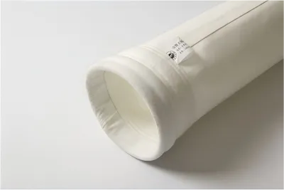
The nominal media area should also be effectively used. Poor inlet distribution can overload some filter bags while leaving others underused.
How Should the Fan Be Selected?
The fan must overcome the resistance of the complete system, including:
Hood entry losses
Duct friction
Elbows and branches
Dampers
Pre-separators
Collector pressure drop
Outlet ductwork
The collector resistance should be based on filters during normal operation, not only when they are clean.
An oversized fan may increase energy consumption, dust loading and equipment wear. An undersized fan may fail to maintain capture and transport velocity. A variable-frequency drive can help balance changing production conditions.
How Large Should the Hopper Be?
The hopper should transfer dust to the discharge device rather than store it for long periods.
The rotary valve or screw conveyor must remove dust faster than the maximum collection rate. If the hopper becomes overfilled, dust may reach the filter section and cause unstable pressure drop.
Dust bulk density and discharge frequency should both be considered when sizing the hopper.
What Information Is Needed Before Equipment Selection?
Reliable industrial dust control design requires the following data:
| Design data | Main purpose |
|---|
| Airflow at each hood | Determines total system airflow |
| Dust concentration | Determines dust load |
| Particle size and density | Influences duct and separator design |
| Temperature and moisture | Determines filter media |
| Chemical composition | Determines corrosion resistance |
| Operating schedule | Identifies simultaneous airflow |
| Emission requirement | Defines filtration performance |
Combustible dust also requires a separate fire and explosion risk assessment.
Common Sizing Mistakes
Frequent design problems include:
Selecting the collector before calculating hood airflow
Using average dust load without considering peaks
Applying the same air-to-cloth ratio to every application
Sizing the fan using clean-filter resistance
Using oversized ducts that allow dust to settle
Treating the hopper as long-term storage
Conclusion
A reliable system begins with correct source-capture airflow. The ductwork must keep particles moving, while dust concentration determines the filter and discharge load.
Filter area should be selected using an application-specific air-to-cloth ratio, and the fan should be sized against the total pressure loss of the operating system.
EnvirontechTS can design an industrial dust collector system based on actual process airflow, dust properties and emission requirements.
FAQ
How is dust collector airflow calculated?
Add the required airflow of all extraction points that operate simultaneously.
What is the formula for filter area?
Divide total airflow by the selected air-to-cloth ratio.
Does higher dust loading require more filter area?
Usually yes, especially for fine or difficult-to-clean dust.
Can a dust collector fan be oversized?
Yes. Excessive airflow increases energy use and filter loading.
Why does dust collect inside ducts?
The conveying velocity may be too low.
Is a cyclone always necessary?
No. It is mainly useful for high dust loads or coarse, abrasive particles.
 English
.webp "Selective Catalytic Reduction")