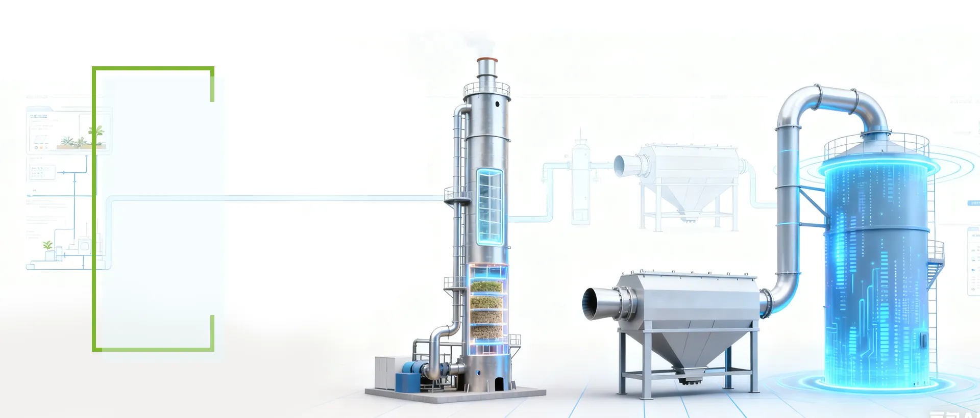
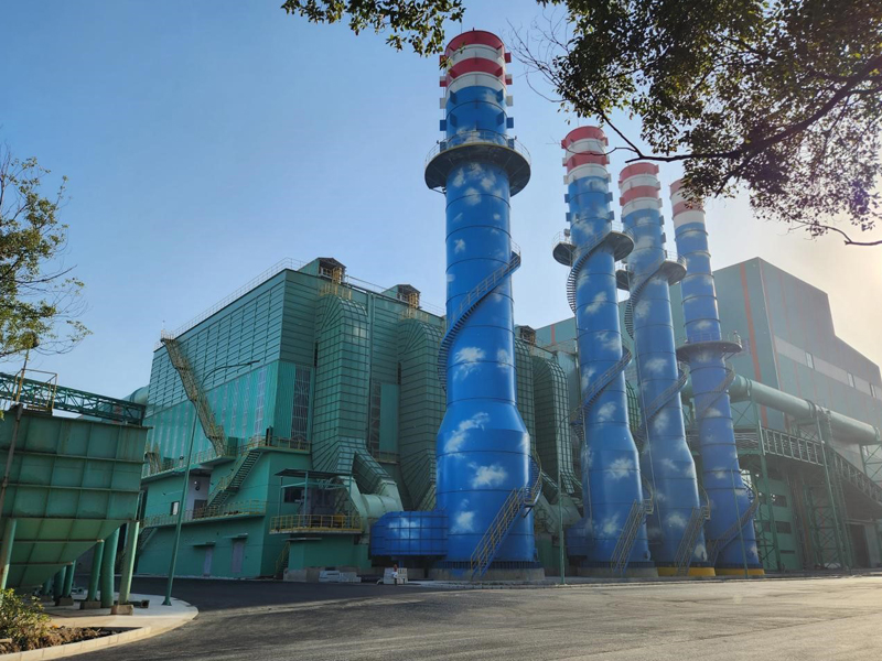
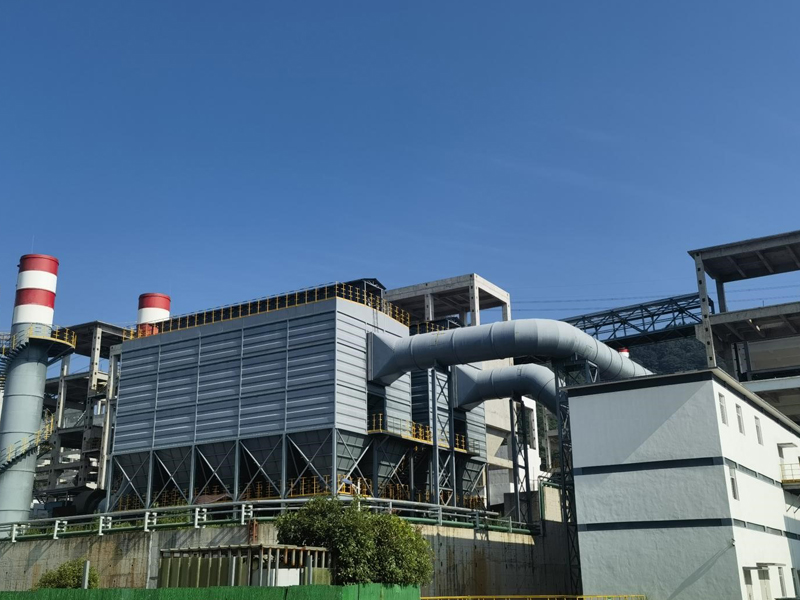
This integrated technical solution combines SDS dry flue gas desulfurization with SCR denitrification to control sulfur dioxide and nitrogen oxide emissions from submerged arc furnaces and other industrial high-temperature processes.
The process route is selected according to flue gas temperature, flow rate, SO₂ and NOx concentrations, dust loading, operating conditions, required outlet limits, and the configuration of the existing dust collection system.
By coordinating desulfurization, particulate collection, catalyst reaction, reagent preparation, and automatic control, Tianshun provides a complete flue gas treatment system designed for stable industrial operation and multi-pollutant emission control.
1. Desulfurization Process Selection
Industrial sulfur dioxide can be treated through wet, semi-dry, dry, or fixed-bed desulfurization processes.
Wet Desulfurization
Common wet processes include limestone-gypsum, ammonia-based, single-alkali, and double-alkali methods. These systems use a liquid absorbent to capture and neutralize SO₂.
Wet desulfurization can provide strong gas-liquid contact, but it may require process water, wastewater treatment, corrosion protection, and reheating before downstream denitrification.
Semi-Dry Desulfurization
Common semi-dry processes include circulating fluidized bed desulfurization and spray dryer absorption. An atomized alkaline slurry reacts with acidic gases while the heat in the flue gas evaporates most of the water.
The dry or low-moisture reaction products are subsequently collected by a particulate control system.
Dry Desulfurization
Dry processes include SDS sodium bicarbonate injection and fixed-bed or moving-bed desulfurization.
For the submerged arc furnace conditions assessed in this solution, wet treatment would increase the temperature-recovery demand before downstream SCR. A fixed-bed route may also provide insufficient reaction efficiency under some high-flow conditions and may create additional particulate-handling requirements.
For these reasons, Tianshun recommends an SDS dry flue gas desulfurization process for this application. It supports efficient sulfur dioxide removal while limiting water consumption and simplifying integration with downstream dust collection and denitrification equipment.
2. SDS Dry Flue Gas Desulfurization Process
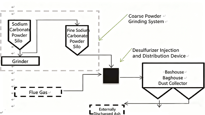
SDS uses finely ground sodium bicarbonate as the desulfurizing agent.
When sodium bicarbonate particles contact hot flue gas, they are thermally activated and converted into sodium carbonate. This thermal decomposition creates a porous reaction product with a larger active surface area, improving contact with acidic gas components.
The primary thermal activation reaction is:
2NaHCO₃ → Na₂CO₃ + H₂O + CO₂
The activated sodium carbonate then reacts with sulfur dioxide, hydrogen chloride, hydrogen fluoride, and other acidic gas components.
This makes SDS suitable for removing sulfur dioxide from flue gas in industrial applications where low water use, dry residue handling, and compact integration are important.
Main SDS Process Steps
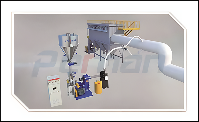
Sodium bicarbonate is stored and accurately metered.
The reagent is ground into fine particles.
Powdered sodium bicarbonate is injected into the hot flue gas duct.
Thermal activation converts sodium bicarbonate into porous sodium carbonate.
Sodium carbonate reacts with SO₂ and other acidic gases.
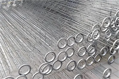
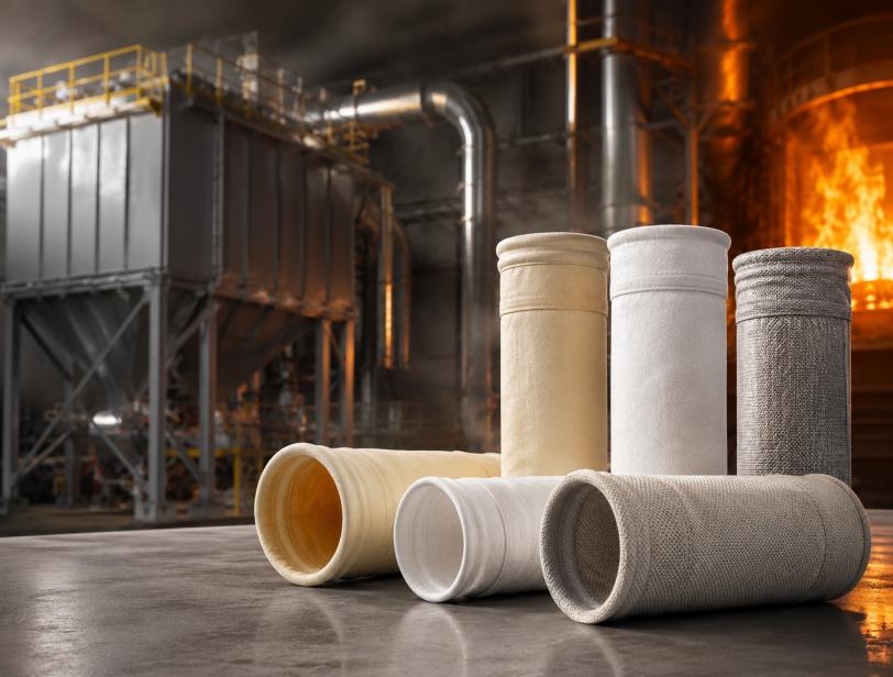
Reaction products and unreacted sorbent are captured by downstream filtration.
Cleaned gas proceeds to the denitrification or final discharge stage.
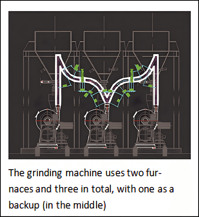
Collection of Desulfurization Ash
The SDS reaction generates dry desulfurization ash that must be captured by filtration equipment.
The main furnace dust collector generally collects valuable microsilica powder. Whether the microsilica and desulfurization ash can be collected together depends on the owner’s reuse, quality, and residue-management requirements.
Two collection configurations can be considered.
Single-Stage Baghouse Configuration
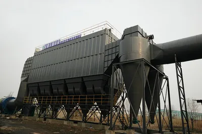
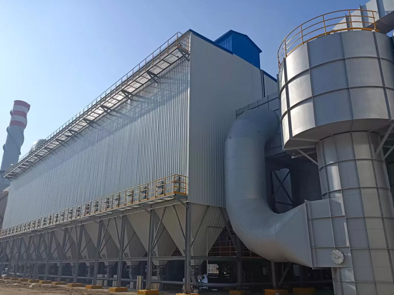
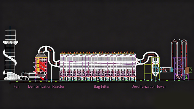
A single-stage bag dust collector collects furnace dust and desulfurization reaction products together.
This configuration has a relatively simple process layout and lower initial equipment requirements, but the mixed residue may have limited reuse value.
Two-Stage Baghouse Configuration
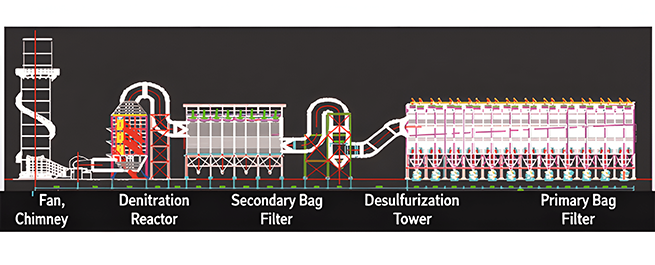
A two-stage filtration system separates microsilica powder from desulfurization ash.
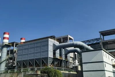
The first-stage collector captures furnace dust or microsilica, while the second-stage collector captures the desulfurization products generated after sodium bicarbonate injection.
This configuration is suitable when the plant needs separate collection, independent reuse, or controlled disposal of the two materials.
3. How NOx Is Formed in Industrial Flue Gas
Nitrogen oxides are generated during high-temperature combustion and thermal industrial processes. The main regulated components are normally nitric oxide and nitrogen dioxide.
The principal NOx formation mechanisms include:
Thermal NOx
Thermal NOx is formed when nitrogen and oxygen in the combustion air react at high temperatures.
Its formation is strongly influenced by peak flame temperature, oxygen concentration, and high-temperature residence time.
Fuel NOx
Fuel NOx is generated when nitrogen compounds contained in fuel or raw materials are oxidized during combustion.
The proportion of fuel NOx depends on fuel composition, combustion conditions, and furnace design.
Process NOx
Certain industrial chemical or metallurgical reactions can also generate nitrogen oxides independently of conventional fuel combustion.
Understanding the dominant NOx formation mechanism helps determine whether combustion optimization, SNCR, SCR, or a combined treatment route should be selected.
4. Industrial NOx Removal Technologies
The main NOx removal technologies can be divided into combustion-stage control and post-combustion flue gas treatment.
Combustion-Stage NOx Control
Combustion-stage technologies reduce NOx formation inside the furnace. Typical measures include:
These methods can reduce the initial NOx load but may not independently meet stringent or ultra-low outlet requirements.
Selective Non-Catalytic Reduction
SNCR injects ammonia or urea into a suitable high-temperature zone without using a catalyst.
Its advantages include relatively simple equipment and lower initial investment. However, its reaction temperature window is narrow, and its NOx reduction performance is generally lower and more sensitive to furnace operating conditions.
Selective Catalytic Reduction
SCR uses a reducing agent and catalyst to convert NOx mainly into nitrogen and water.
For applications requiring deeper and more stable treatment, selective catalytic reduction for NOx control can provide better adaptability to stringent emission requirements.
Combined SNCR and SCR
A combined route may use SNCR as the first reduction stage and SCR as the downstream polishing stage.
This configuration can reduce catalyst load and reagent demand in projects with high inlet NOx concentrations, but it requires coordinated temperature and reagent control.
5. How the SCR Process Works
The SCR process begins by preparing and injecting ammonia, ammonia water, or ammonia generated through urea hydrolysis.
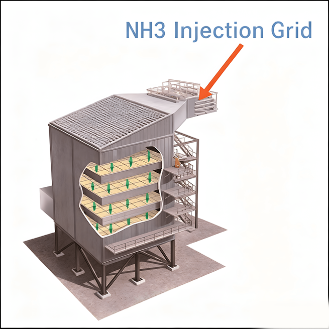
The reducing agent is distributed evenly across the flue gas section through an ammonia injection grid. The mixed gas then enters the SCR reactor and passes through the catalyst layers.
On the catalyst surface, ammonia reacts selectively with NOx and converts it mainly into nitrogen and water.
A complete SCR NOx reduction process normally includes:
Reducing-agent storage and preparation
Reagent metering
Ammonia injection
Dilution-air supply
Uniform ammonia-flue gas mixing
Catalyst reaction
Soot removal or catalyst cleaning
Outlet NOx and ammonia-slip monitoring
A properly designed system supports stable SCR NOx removal while controlling reagent consumption, pressure drop, catalyst contamination, and ammonia slip.
6. Key Design Factors for SCR NOx Control
Effective SCR NOx control depends on several connected design and operating parameters.
Flue Gas Temperature
Each catalyst formulation has a suitable active temperature range.
If the gas temperature is too low, reaction activity may decline and ammonium salts may form. If it is too high, catalyst aging or unwanted reactions may increase.
The catalyst type and reactor location should therefore be selected according to the actual temperature profile rather than a single nominal temperature.
Sulfur Content
Sulfur dioxide and sulfur trioxide can react with ammonia and form ammonium salts.
These deposits may increase pressure loss, contaminate catalyst surfaces, affect downstream equipment, and shorten catalyst service life.
Upstream desulfurization performance must therefore be coordinated with the SCR system.
Dust Loading
High dust concentration can cause erosion, blockage, and deposition on catalyst channels.
The design should consider dust particle size, abrasiveness, ash composition, gas velocity, catalyst pitch, and the location of upstream dust removal equipment.
Ammonia Distribution
Uneven ammonia distribution can create untreated gas zones and local over-injection.
A correctly designed ammonia injection grid should provide uniform distribution across the entire flue cross-section.
Computational flow analysis, adjustment valves, static mixers, and outlet sampling grids may be used to improve distribution.
Catalyst Cleaning
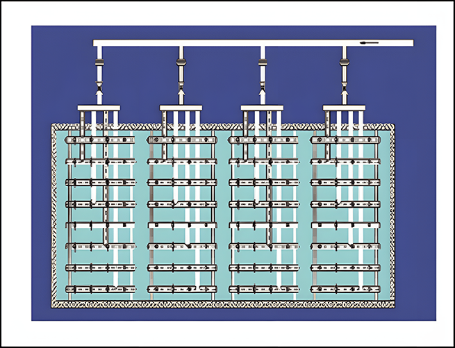
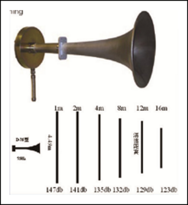
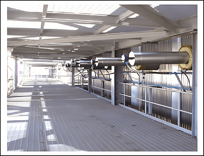
Dust deposition can be controlled using sonic soot blowers, steam soot blowers, compressed-air systems, or other cleaning equipment selected according to the catalyst and flue gas conditions.
Reducing-Agent Selection
Liquid ammonia, ammonia water, and urea differ in safety requirements, storage conditions, capital investment, energy consumption, and operating cost.
The final selection should consider local regulations, plant safety standards, reagent availability, required capacity, and operator experience.
These design factors determine the reliability of the complete SCR emission control system.
7. Comparison of NOx Control Technologies
| Technology | Main principle | Typical performance level | Main advantages | Main limitations |
| Low-NOx combustion | Reduces NOx formation during combustion | Low to moderate | No separate downstream catalyst reactor | May not meet stringent outlet limits independently |
| Air or fuel staging | Controls oxygen and fuel distribution | Low to moderate | Can be integrated into furnace operation | May affect combustion stability |
| Flue gas recirculation | Returns part of the flue gas to reduce flame temperature | Low to moderate | Reduces thermal NOx formation | Requires fan capacity and process integration |
| SNCR | Injects ammonia or urea without a catalyst | Moderate | Simpler system and lower initial cost | Narrow temperature window and higher ammonia-slip risk |
| SCR | Uses catalyst-assisted reduction | High | Suitable for deep and stable NOx control | Requires catalyst management and temperature control |
| SNCR + SCR | Combines furnace-stage and catalyst-stage treatment | High | Reduces load on the SCR reactor | Higher system complexity |
Actual performance must be confirmed according to inlet NOx, gas temperature, residence time, reagent distribution, catalyst configuration, and required outlet limits.
8. SCR Catalyst Types and Installation
The catalyst is the core reaction component of the SCR system.
Typical structures shown in this solution include:
Honeycomb Catalyst
Honeycomb catalyst provides a large reaction surface within a compact volume. Channel pitch can be selected according to dust concentration and blockage risk.
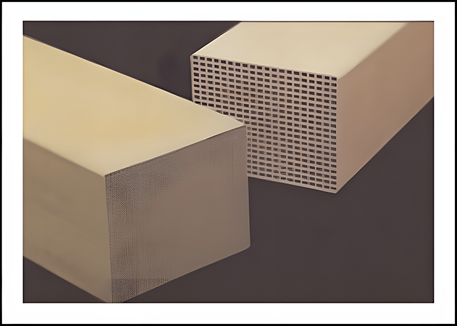
Plate Catalyst
Plate catalysts have relatively open gas passages and can be suitable for dusty flue gas applications where resistance to blockage is important.
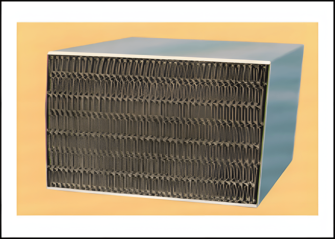
Corrugated Plate Catalyst
Corrugated structures combine reaction surface area with larger gas channels. Their suitability depends on dust loading, temperature, and catalyst formulation.
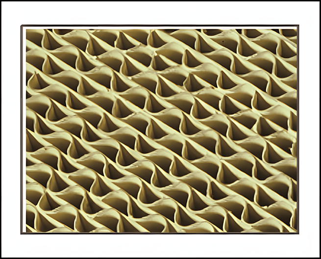
Other Structured or Pellet Catalysts
Other catalyst forms may be selected for specific gas compositions, pressure-drop requirements, reactor layouts, or lower-dust applications.
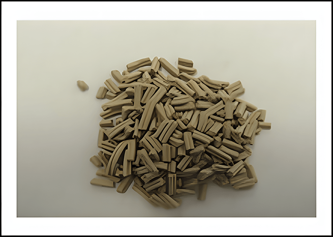
Catalyst selection should consider:
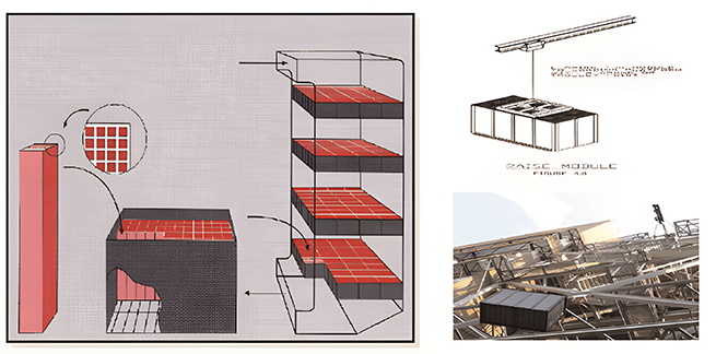
9. SCR Catalyst Module Design
A modular catalyst structure simplifies transportation, installation, inspection, and replacement.
A well-designed SCR catalyst module should:
Maintain catalyst blocks in a stable arrangement
Support uniform gas distribution
Limit bypass leakage around the catalyst
Allow convenient lifting and installation
Reduce reactor maintenance time
Enable staged replacement of individual modules
Reserve space for future catalyst layers when required
Modular design can shorten shutdown time because individual units can be removed and replaced without dismantling the entire reactor.
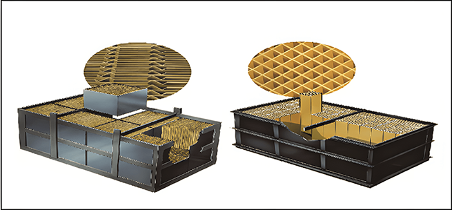
10. SCR Equipment and Catalyst Assembly
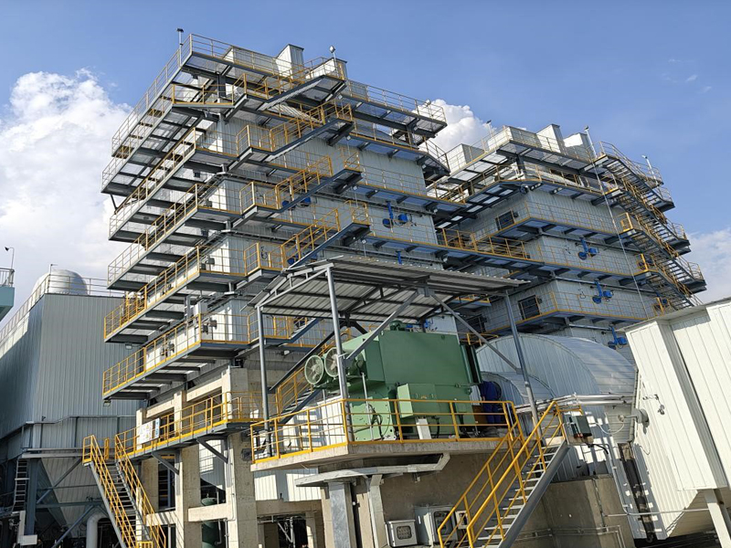
The reactor assembly normally includes catalyst modules, supporting beams, sealing plates, lifting structures, inspection access, soot-blowing equipment, and differential-pressure monitoring points.
Critical SCR equipment should be arranged to support:
Safe catalyst installation
Uniform loading of structural supports
Convenient inspection and maintenance
Reliable sealing between modules
Controlled gas bypass
Access for soot removal
Future catalyst replacement
Before operation, the assembled catalyst layers should be inspected for installation alignment, seal integrity, physical damage, channel blockage, and foreign objects.
11. Reducing-Agent Selection and Ammonia System
The reducing-agent system supplies ammonia to the SCR reactor at a controlled rate.
Common options include:
Liquid Ammonia
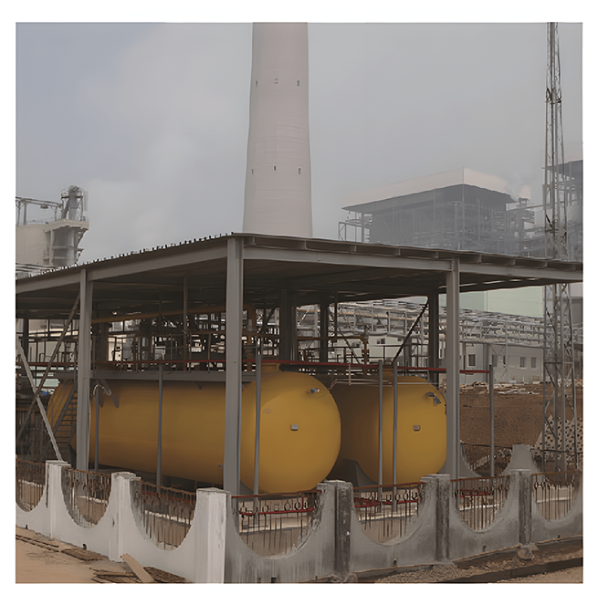
Liquid ammonia generally has relatively low reagent cost and compact storage volume. However, it is toxic and requires pressure storage, strict safety controls, leakage monitoring, emergency systems, and compliance with applicable regulations.
Ammonia Water
Ammonia water is stored under lower pressure but contains a large proportion of water. It may require larger tanks and more energy for evaporation.
Urea
Urea is stored as a stable solid and is generally easier to transport and handle. However, the system requires dissolution, hydrolysis or pyrolysis equipment and additional energy to generate ammonia-containing gas.
Urea Hydrolysis Process
The urea hydrolysis process generally includes:
Urea particle storage
Urea conveying
Urea dissolution
Urea solution storage
Urea solution metering
Hydrolysis reaction
Ammonia-containing product gas transportation
Dilution-air mixing
Ammonia injection into the flue gas
Urea is dissolved with treated water to produce a controlled-concentration solution. The solution is transferred to the hydrolysis reactor, where heat generates ammonia-containing product gas.
The product gas then passes through the metering and dilution system before entering the ammonia injection grid.
Reducing-Agent Comparison
| Factor | Liquid ammonia | Ammonia water | Urea |
|---|
| Storage condition | Pressurized liquid | Atmospheric or low-pressure liquid | Dry solid |
| Safety management | Highest requirement | Moderate requirement | Relatively lower storage risk |
| Storage volume | Relatively compact | Larger | Moderate |
| Preparation equipment | Evaporation and dilution | Evaporation and dilution | Dissolution and hydrolysis |
| Energy demand | Relatively low | Moderate to high | Higher due to hydrolysis |
| Transport | Specialized | Bulk liquid transport | Convenient solid transport |
| Suitable projects | Large systems with complete safety infrastructure | Medium systems with available storage space | Projects prioritizing safer storage and transport |
The selection should be made through a lifecycle assessment rather than reagent price alone.
12. Main Components of the Ammonia Supply System
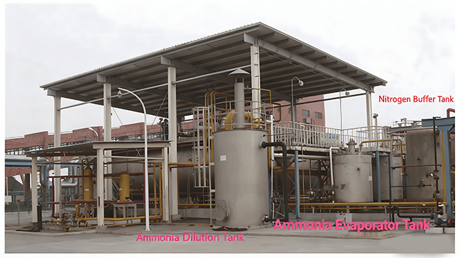
Depending on the selected reducing agent, the system may include:
Unloading compressor or unloading pump
Reagent storage tank
Ammonia evaporator
Ammonia buffer tank
Urea dissolving tank
Urea solution storage tank
Urea hydrolysis reactor
Ammonia-air mixer
Dilution-air fan
Metering module
Ammonia injection grid
Wastewater or drainage tank
Pipelines, valves, instruments, and safety devices
Leakage detection and emergency systems
Keep the existing ammonia storage and unloading project images here.
13. Information Required for a Customized Solution
To design an integrated desulfurization and denitrification system, buyers should provide:
Normal and maximum flue gas flow
Normal and maximum gas temperature
Inlet SO₂ concentration
Required outlet SO₂ concentration
Inlet NOx concentration
Required outlet NOx concentration
Dust concentration and particle characteristics
Moisture and oxygen content
Sulfur trioxide and acid-gas content
Daily and annual operating hours
Existing dust collector configuration
Fuel and raw-material information
Available installation space
Available power, water, steam, and compressed air
Preferred reducing agent
Applicable emission standards
Tianshun can then determine the desulfurization process, sorbent consumption, dust-collection configuration, catalyst type, reactor size, reducing-agent system, and automatic-control requirements.
Conclusion
This technical solution combines SDS dry flue gas desulfurization with SCR denitrification to support integrated SO₂, NOx, and particulate control.
Sodium bicarbonate injection provides dry sulfur dioxide removal, while the downstream baghouse captures reaction products. The SCR reactor then uses a controlled reducing-agent supply and catalyst system to provide deep SCR NOx reduction.
The final configuration should be based on actual flue gas parameters, emission targets, plant utilities, residue requirements, safety conditions, and lifecycle operating cost.
For broader DeNOx system options, review Tianshun’s flue gas denitrification solutions or submit your flue gas data for a customized technical proposal.
Frequently Asked Questions
What is SDS dry flue gas desulfurization?
SDS is a dry process that injects finely ground sodium bicarbonate into hot flue gas. The reagent is thermally activated into porous sodium carbonate, which reacts with SO₂ and other acidic gases.
Why is SDS suitable before an SCR system?
SDS reduces sulfur compounds without adding significant moisture or requiring a wet absorber. This can simplify temperature management and reduce the risk of sulfur-related deposits in the downstream SCR system.
What is the main difference between SNCR and SCR?
SNCR reduces NOx without a catalyst and requires a narrow high-temperature reaction zone. SCR uses catalyst modules to support deeper and more stable NOx reduction at a suitable lower temperature.
What affects SCR catalyst module selection?
Key factors include temperature, dust loading, sulfur content, catalyst poisons, required NOx reduction, channel pitch, pressure drop, cleaning method, and expected catalyst life.
Can SCR equipment use either ammonia or urea?
Yes. Liquid ammonia, ammonia water, and urea can all provide the reducing agent, but they differ in storage safety, preparation equipment, energy consumption, and operating cost.
 English